Project One: Blinking Heartbeat Box
In this first project, you will build a circuit and learn how to use code to control a light. Electrical current is under your command with the right code words! Before we dive into the code, let’s take a look at how to build a circuit, a path for electricity to flow.
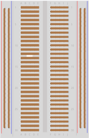
Solderless breadboards have built-in metallic strips. These strips act like wires to connect pieces you add to the circuit, like lights and motors. Underneath the plastic grid, the metallic strips are arranged like this:
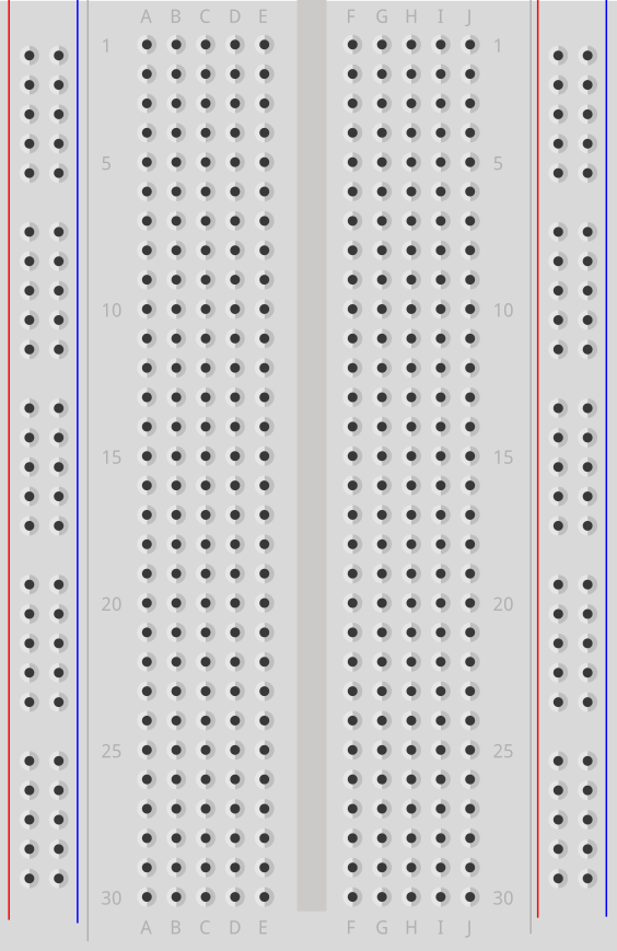
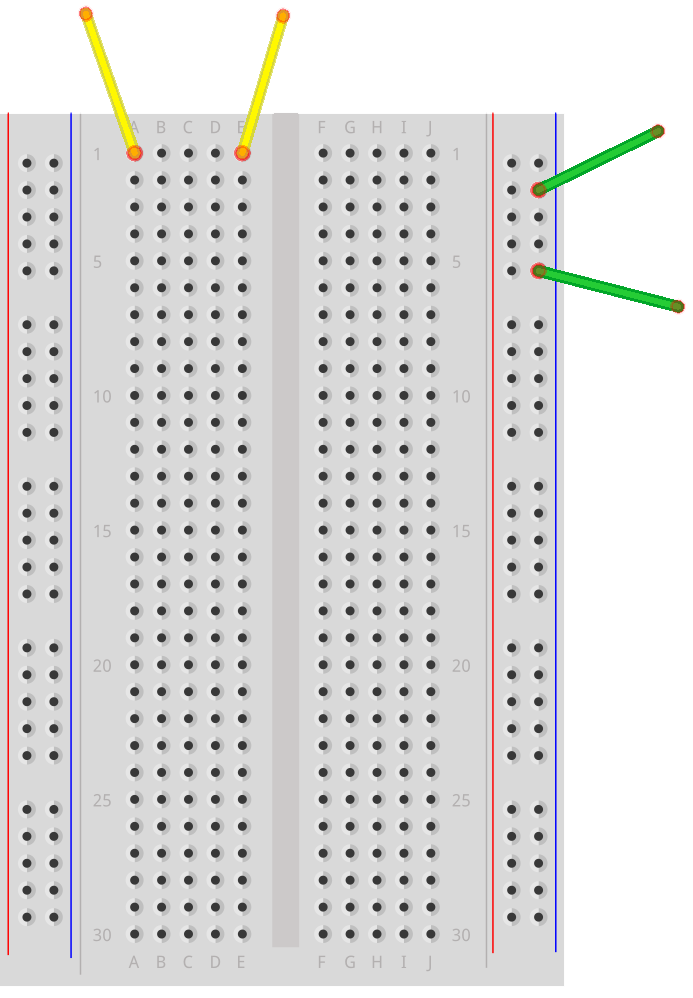
Which means that although each pair of colored wires are plugged into different breadboard holes, the conductive strip connects each pair:
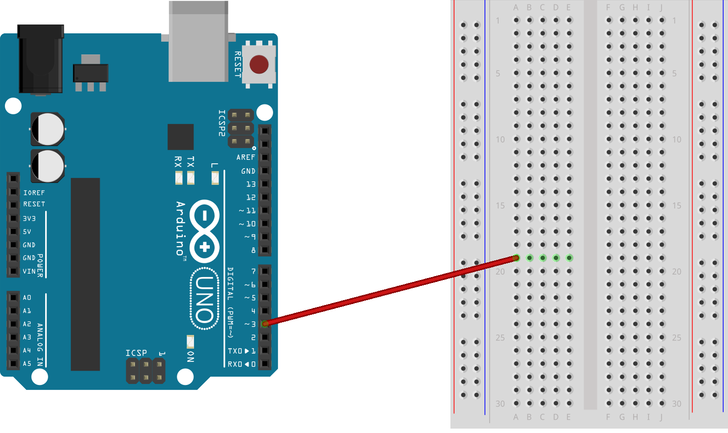
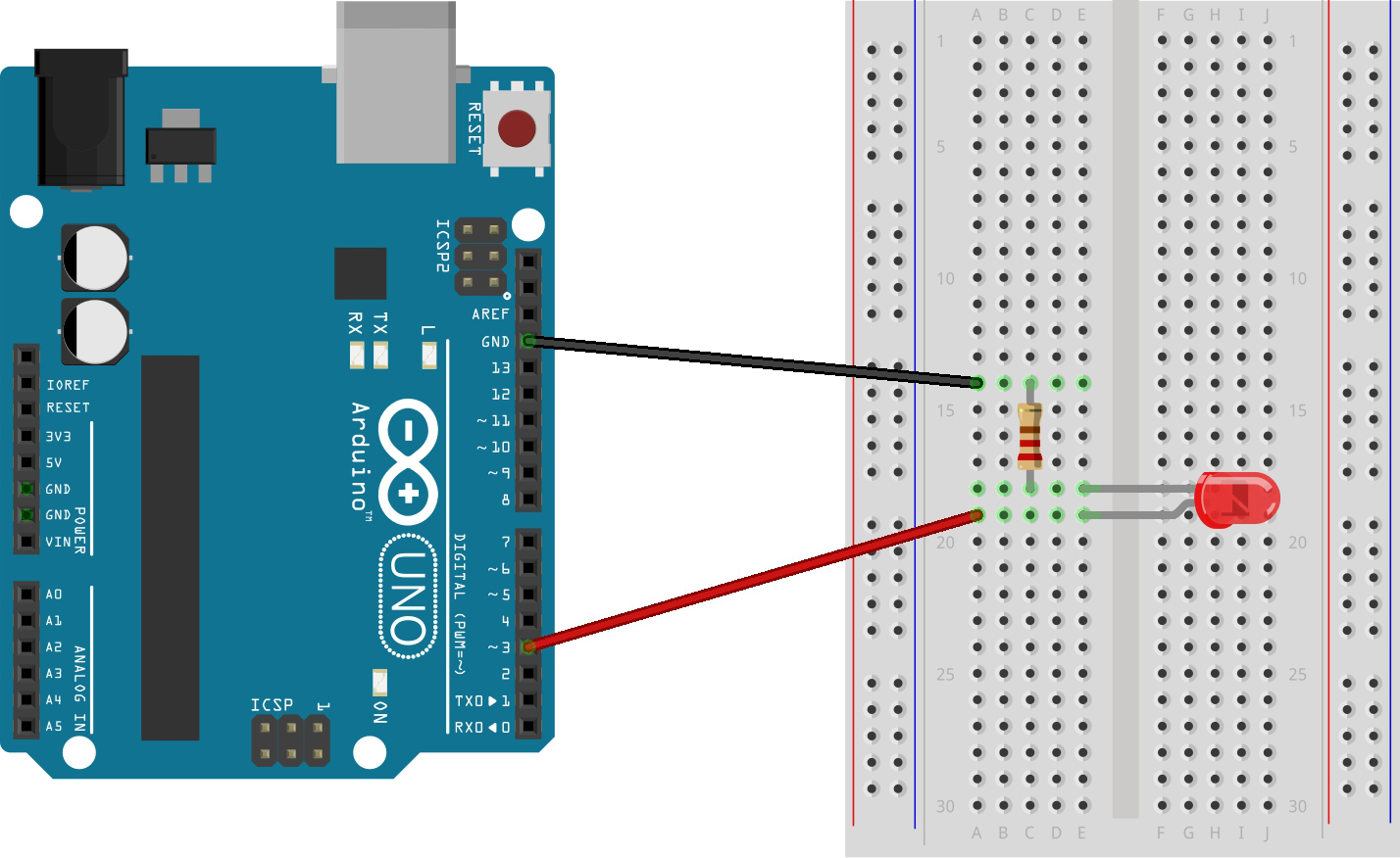
Solderless breadboard circuits are easy to assemble, disassemble, and reuse, so they will be your base for most projects in this book. Start by inserting one end of a wire into digital pin 3 on the right side of the Arduino. Place the other end of the wire into any hole in the breadboard (except for the two vertical strips on either side -- these are used to make more connections to your power source).
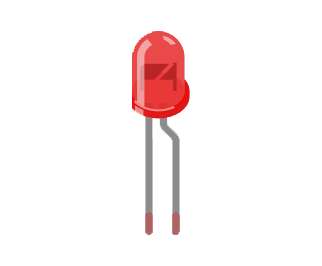
Next, look at the legs of the light-emitting diode (LED for short). The long leg, known as the anode, is usually called the positive end, which means it should be connected to power. The shorter leg, known as the cathode, is the negative end and will be connected to ground. We'll learn how to connect to power and ground next.
Circuit Tip
Diodes are like one-way street signs for current. If a diode is connected backwards, no current can flow, and your LED cannot light up!
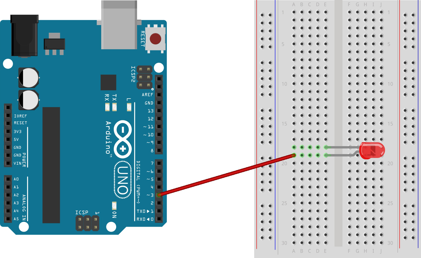
Connect the LED so that the long leg is in the same row as the power wire. Because electricity moves across the rows in your breadboard, electric current will be able to flow from the Arduino to the LED. Insert the shorter leg in any row besides the previous row. Your setup should look something like the board below.
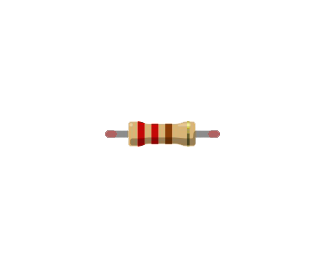
The next piece is a resistor. As the name suggests, resistors resist the flow of current by transforming electrical energy into thermal energy (heat). Without a resistor, the high current would burn out the LED. Resistors’ colored stripes tell you exactly how much they resist current flow. Find a resistor with two red stripes, a brown stripe, and a gold stripe: this is a 220 Ohm resistor (Ohm is a unit of measurement, represented by Ω). If you don't have a 220Ω resistor, you can use a slightly higher value, like 330Ω.
Connect one end of the resistor to the LED’s short leg. Resistors aren’t one-way streets like LEDs are, so it does not matter which end of the resistor you connect.
Finding the Right Resistor
To calculate the resistance needed, we use Ohm’s Law, which says that voltage (V) divided by current (I) equals resistance (R). Different colors of LEDs require different amounts of current. We’ll try a calculation with a yellow LED rated at 20 milliAmps that uses a digital pin’s standard output of 5 Volts.
5 Volts / .002 Amps = 250 Ohms
Common resistor values nearby are 220 or 330 Ohms. Try a resistance calculation for your favorite color of LED!
Finally, insert a new wire into the same row as the resistor’s free end. Connect the other end of this wire to the digital pin labeled GND (ground) on the Arduino’s right side. There is now a closed circuit: a complete path for current to flow from the power source, through the LED, and back to ground. After we add code and power in the next step, electricity will flow from your power source (the computer) and through the Arduino’s digital pin. Digital pins have only two states: HIGH (on; 5 Volts) or LOW (off; 0 Volts). When the pin is programmed to be HIGH, current will want to flow towards ground through the LED. When the pin is LOW, there is no voltage output, so there can be no current, and the LED will turn off.
Now, let’s give the Arduino some power and light up the LED! Plug one end of the USB cord into the Arduino and the other into the computer’s USB port. Open the Arduino application or browser app you set up in Getting Started. If this is your first time using the browser editor, select "Web Editor" if prompted.

Arduino programs are called sketches. Copy the following code into your sketch:
#define ledPin 3void setup(){pinMode(ledPin, OUTPUT);}void loop(){digitalWrite(ledPin, HIGH);delay(1000);digitalWrite(ledPin, LOW);delay(1000);}
Coding Tip
Computers aren’t very smart, so you must follow specific syntax rules when writing code. Words are case-sensitive, and commands must be followed by a semicolon. However, the amount of whitespace between words does not matter. For example,
delay(1000);
will work the same way as
delay( 1000 ) ;
If you're stuck, take a look at the video below to get back on track.
Once the code is inside your sketch, you’re ready to transfer those instructions to your Arduino.
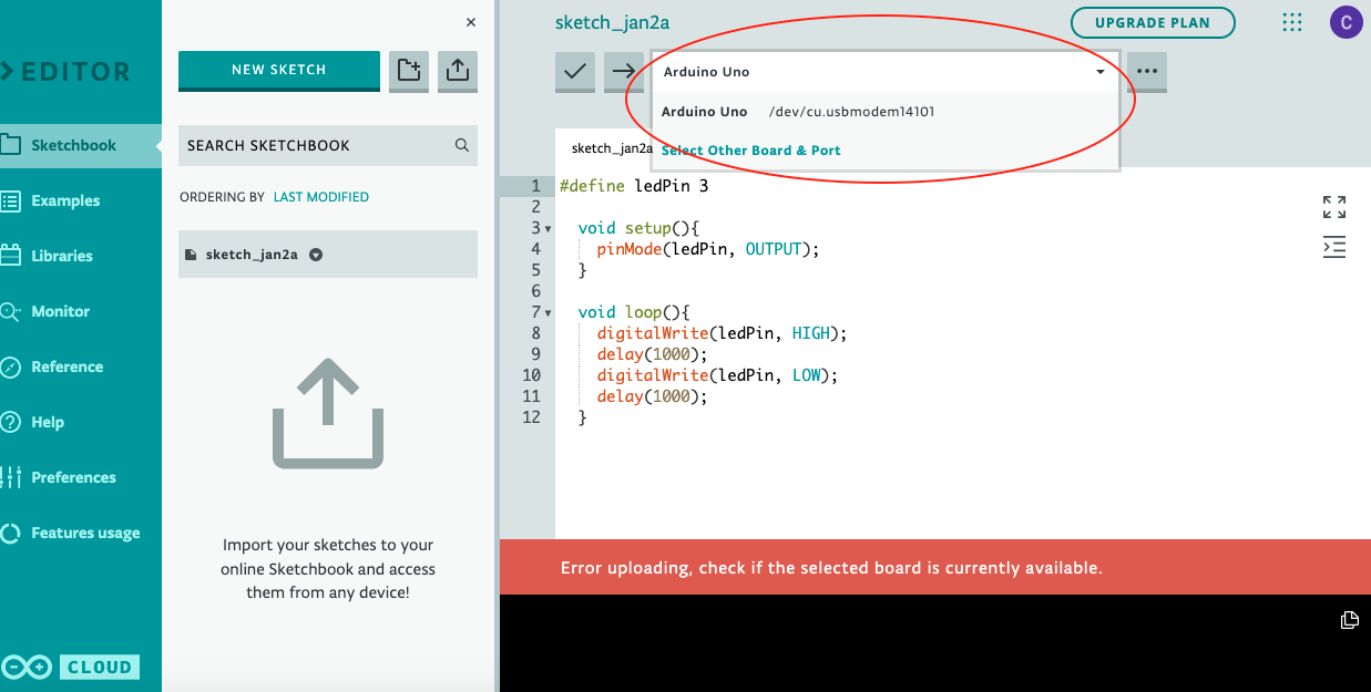
If you're using the browser app, select "Arduino Uno" from the drop down menu. Once your microcontroller is plugged in, you should also see a Port show up in the drop down menu (possibly something like /dev/cu.usbmodem14101).
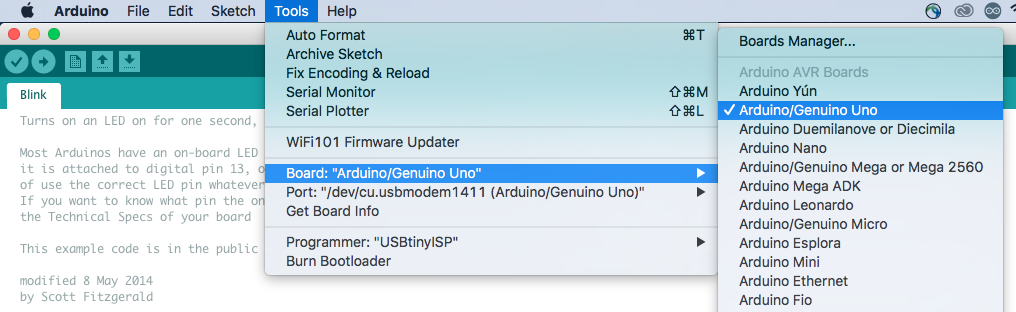
If you're using the downloaded Arduino app, select Board > Arduino Uno from the Tools menu.
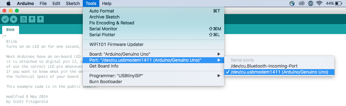
Return to the Tools menu and select Port. You should see a new port, possibly with “USB” in the name. If you’re not sure which port to select, try each one until your code successfully uploads.
Now click the “Upload” arrow button in the top left corner, next to the check mark button. This button will first compile the code, converting it into a language that the Arduino can understand. The compiler also checks for errors in the code, such as missing semicolons, that would confuse the computer. Compilers only check that the syntax of the code is correct. Successful compilation is not a guarantee that the code will actually behave as you intended!
If the circuit is correct and the code has successfully uploaded, your LED will start to flash!
If you see an orange error bar at the bottom of your screen, there was an issue with compiling the code or uploading it to the board. Error messages are meant to help you identify the cause of your problem. If the error refers to a specific line of your code, you probably have a typo. Check your code carefully against the code above.
If you don’t see an error message but your LED does not light up, check to make sure your LED’s longer leg is connected to power (is it in the same row as the wire connected to pin 3 on the Arduino?) Also check that you have connected the resistor to the digital GND pin on the right side of the board instead of the power GND pin on the left side of the board.
Coding Tip
The numbers inside the delay() function are called parameters. You can edit the parameters to change the way the function behaves. How could you change the delay to 500 milliseconds? 250 milliseconds? Upload the code again with the new parameters to see your changes.
Congratulations! You’ve made an important step towards building interactive circuits. Once the LED is blinking, you can get creative with making it into a decoration. To make a heartbeat box, change the parameters of the delay() function to beat as fast or slow as you would like. Cut out a heart shape from one side of a cardboard box, and tape red tissue paper or construction paper behind the hole. Your blinking LED will illuminate the heart with a steady pulse.
Looking for an extra challenge? Try copying the code below to spell a secret message in morse code.
#define ledPin 3void setup(){pinMode(ledPin, OUTPUT);}void loop(){blinkS();blinkO();blinkS();}void dot(){digitalWrite(ledPin, HIGH);delay(300);digitalWrite(ledPin, LOW);delay(500);}void dash(){digitalWrite(ledPin, HIGH);delay(1000);digitalWrite(ledPin, LOW);delay(500);}void blinkS(){dot();dot();dot();}void blinkO(){dash();dash();dash();}