Project Five: Desk Fan
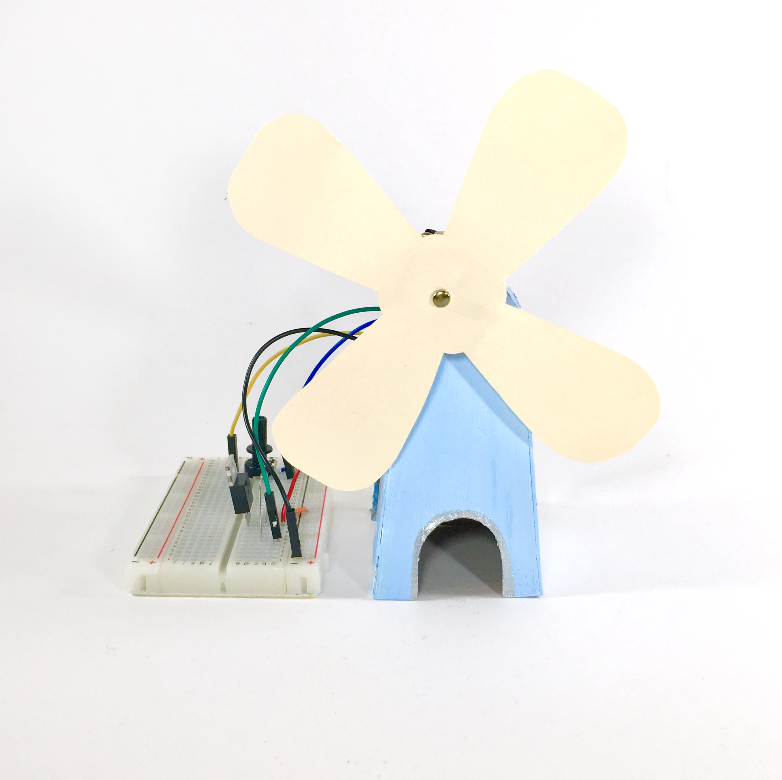
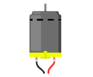

DC (direct current) motors are high-speed motors that produce magnetic fields in order to rotate. Unlike the servo motor from Project Three, DC motors continuously rotate 360 degrees, making them a common choice for powering wheels and other rotating machines. In this project you’ll take advantage of the full circular motion to build an adjustable-speed fan.
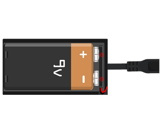
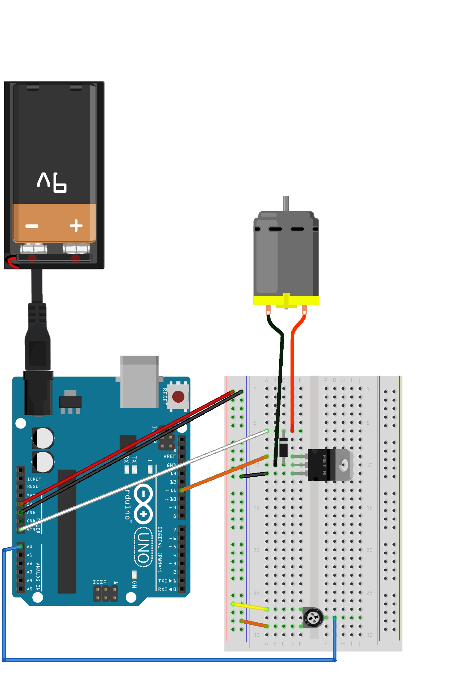
Different brands of motors need different amounts of current, and it’s possible for your motor to draw too much current for a computer’s USB port to handle. A 9V battery will ensure your motor gets enough power. This kind of external battery can plug directly into the Arduino's RCA port. The battery’s voltage is accessible through the Vin pin on the left side of the Arduino.
There are three other new elements in this circuit: a transistor, a potentiometer, and a diode.
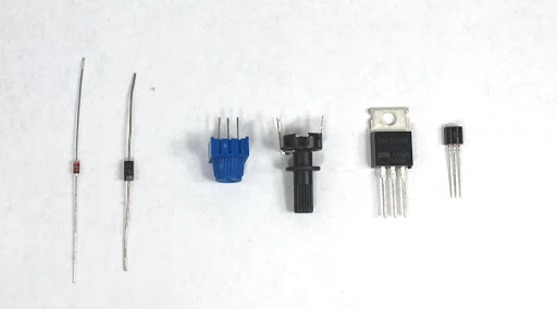
A transistor is like a switch that you’ll use to interface between the high-voltage battery and the lower-voltage Arduino. MOSFET transistors have three legs called the gate, source, and drain (or base, emitter, and collector on other types of transistors). Applying voltage to the gate connects the source and drain pins, allowing current to flow between the two. Your Arduino will control the gate voltage to change the motor speed.
Circuit Tip
If you come across an unfamiliar transistor, search the Web for its part number. Publicly available datasheets will explain which pin is which.
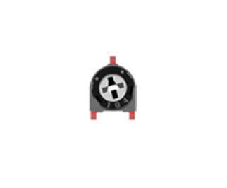
As humans, we need a physical way to tell the Arduino that we want to change the motor speed, and by how much. Potentiometers are knobs whose resistance changes as you rotate them. Just as we used analogRead() in Project Four to read the amount of light in a room, the reading of a potentiometer’s resistance tells us how much the knob has been turned. Potentiometers are a great user interface for controlling variable outputs like speed, volume, amount of light, and more.
The final new element is the diode, which is like a one-way street sign for current flow. Motors continue to spin for a few moments after current is removed, and in this time they generate currents in the opposite direction as before; a diode will protect the circuit from being damaged by this reverse current. Diodes have a specific polarity (just like LEDs, which are diodes that must be inserted in the right direction). The stripe on a diode indicates the cathode (negative end). Just like LEDs, these diodes will not allow any current to flow if they are inserted backwards.
The Arduino’s digital pins only output two voltages, HIGH and LOW. However, we can get an output somewhere in the middle by rapidly switching between HIGH and LOW. For example, to our slow human brains, flickering a light on and off hundreds of times a second would look like a dimmer version of the always-on light. The Arduino has a few pins specifically made for this type of flickering: Pulse Width Modulation (PWM) pins, indicated with a ~ symbol.
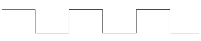
A PWM wave is a square wave with a Duty Cycle describing how often the signal is HIGH (on) or LOW (off). For example, a wave with a duty cycle of 50% looks like this:
While a duty cycle of 20% looks like this:
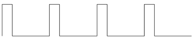
The smaller your duty cycle, the slower your motor will rotate.
The analogWrite() function writes a PWM wave with a duty cycle between 0 (always LOW) and 255 (always HIGH) to a digital pin. When your potentiometer is turned all the way to one side, we send the minimum duty cycle, and when the potentiometer is turned all the way to the other side, we send the maximum duty cycle. The map() function takes the potentiometer’s analog reading, which can be anywhere from 0 to 1023, and proportionally transforms it into a duty cycle value from 0 to 255.
    #define transistorPin 11 // Must be a PWM (~) pin.
    #define potPin A0

    void setup() {
      pinMode(transistorPin, OUTPUT);
    }

    void loop() {
      int potPinReading = analogRead(potPin);
      int fanSpeed = map(potPinReading, 0, 1023, 0, 255);
      analogWrite(transistorPin, fanSpeed);
    }
Once your battery is attached and your code is uploaded, gently rotate the potentiometer knob and watch your motor change speed!
To make the fan blades, cut out the pattern on the next page on sturdy poster board or cardboard. Punch a small hole in the center with scissors or a pen to accommodate the motor shaft. It’s best to start with a small hole and gradually widen it as necessary until the disc fits snugly around the shaft. Use some tape or glue to secure the motor shaft to the fan blades. Always disconnect the circuit from power while attaching anything to the motor.
Make It Yours
Could you use a temperature sensor to automatically turn the fan on when it gets hot enough? Do some fan shapes propel air better than others?
