Project Four: Light Sensitive Bats
It’s time to experiment with sensors! In this project, you’ll make a bat that flaps its wings when the room gets dark enough. A helpful component for measuring the amount of light in an environment is the photoresistor, also sometimes called a photocell or light-dependent resistor. Photoresistors are similar to the resistors you’ve used in previous projects, except their resistances change depending on the intensity of light hitting their surfaces. Dark conditions yield high resistances that become lower and lower as more light is introduced. The Arduino can detect and act on the voltage changes that result from these resistance changes. To understand how, we need to talk about digital and analog signals.
In the world of electronics, digital means binary: digital values are either 0 or 1, on or off. The digital pins you’ve been using on the right side of the Arduino either output HIGH or LOW voltage; there is no third option. Analog, on the other hand, is more of a sliding scale. In the world of Arduino, analog values are anywhere from 0 to 1023 (corresponding to 0V - 5V). This flexibility is helpful for getting more specific data about the world around you. For example, the photoresistor in this project might output values less than 100 in a dark room, around 400 in a reasonably well lit room, and 700 or higher in an extremely bright room. This level of detail gives us much more control over how our circuit behaves.
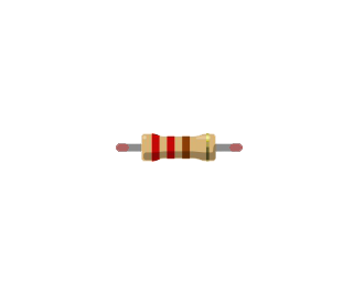
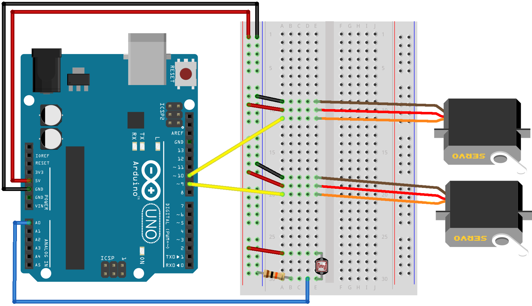
Just like a regular resistor, it does not matter which end of the photoresistor connects to power or ground. Construct the circuit below before moving on.
Most of the code in this project will be familiar to you if you’ve already completed Project Three. Two new additions are analog input and the serial monitor.
As we discussed above, the voltage reading coming out of the photoresistor is proportional to the amount of light in the room. The analogRead() function interprets this value as a number between 0 and 1023. The code below checks if this value is less than 300 -- a reasonable threshold for a bright room -- before telling the servos to move. However, your particular environment or photoresistor might cause this threshold value to be different. We can check exactly what values the Arduino is receiving by using the serial monitor.
The serial monitor is your Arduino’s way of communicating with you. By adding some extra code, we can tell the program to print specific values, or even entire phrases, to the screen. First, Serial.begin(9600) on line 14 helps the Arduino and computer agree that they will communicate with the common language of 9600 baud (bits per second). Then, Serial.println(lightVal) on line 20 tells the Arduino to send us the value of the lightVal variable to print on the screen. Once your program is uploaded, you can click the serial monitor icon on the upper right side of the screen to view the information in real time.

Let’s start gathering information from our photoresistor. Copy the code below into your sketch.
#include <Servo.h>#define servoPin1 9#define servoPin2 10#define photoPin A0#define minAngle 70#define maxAngle 110Servo servo1, servo2;int lightVal;void setup() {servo1.attach(servoPin1);servo2.attach(servoPin2);Serial.begin(9600);}void loop() {lightVal = analogRead(photoPin);Serial.println(lightVal);if (lightVal < 300){servo1.write(minAngle);servo2.write(maxAngle);delay(1000);servo1.write(maxAngle);servo2.write(minAngle);delay(1000);}}
After uploading the code, look at the serial monitor. Try covering the photoresistor with your finger or turning off the lights to watch how the values change. When the readings are low enough, the servos will start to move. If you’d like to make the bat fly in brighter rooms, simply change the threshold value in line 20 to be a higher number. You can also experiment with the delay() parameters or minAngle and maxAngle values to change how hard and fast the bat flaps.
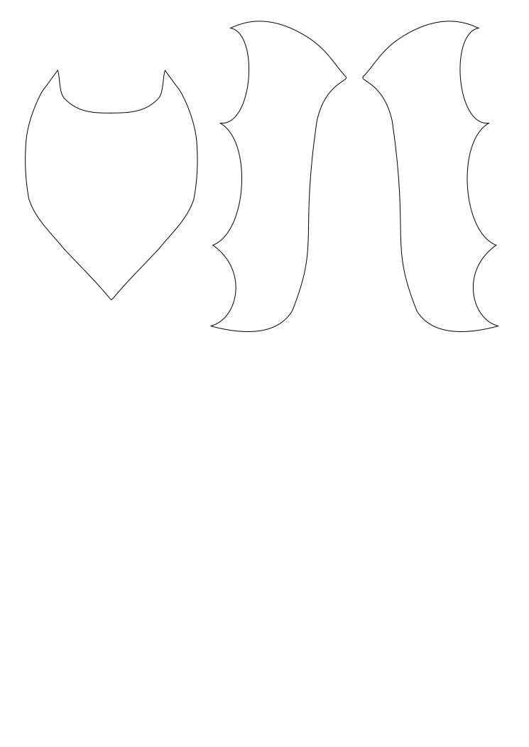
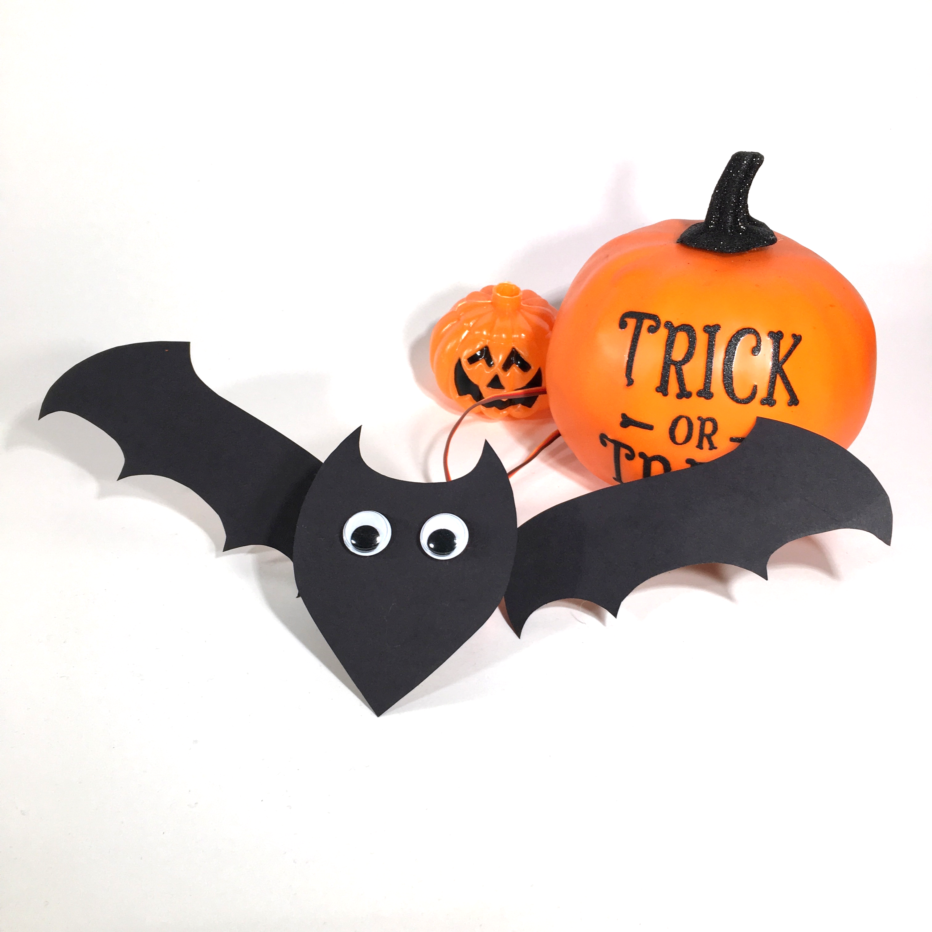
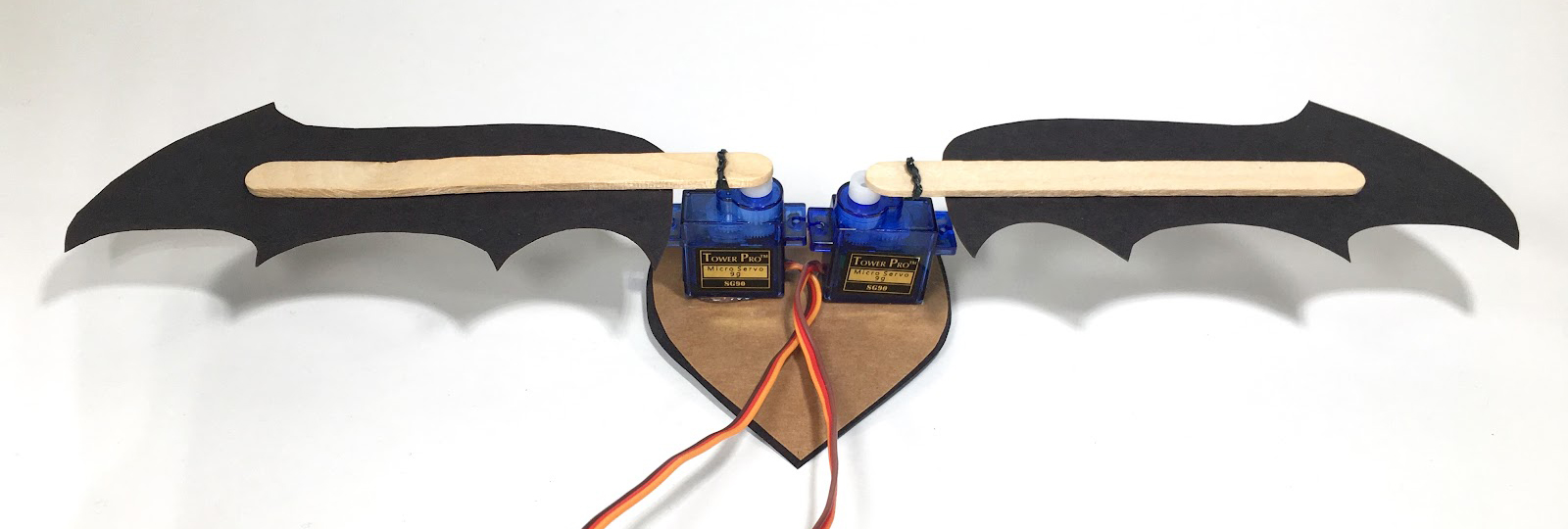
Use rubber bands to attach a popsicle stick to each of the servo arms. Cut out the bat template pieces on the next page. Glue one wing to each of the popsicle sticks, with the front of the wing on the same side as the servo arm. Hot glue the bottom of each servo to the back side of the bat body piece as shown below.
Great job, you’ve created your first circuit that reacts to the world around you! Learning how to use sensors is an important step towards building more interactive circuits.
Print and trace the template below and cut out on cardboard or construction paper, or design your own bat shape.